



Hangzhou Ocean Industry Co., Ltd. is one of the leading manufacturers and suppliers of conveying chain for cement industry in China. Welcome to wholesale bulk durable industrial chains and power transmission parts made in China here from our factory. All customized products are with high quality and competitive price.
Cement Industry Conveyor Chains
Cement plants move more tonnage on chain than on any other component. Raw meal, clinker and finished cement all travel on bucket elevators and central lifting chains, and the chains work in the one environment that shortens their life fastest: a continuous cloud of abrasive dust.
This page covers the three chain families we supply for that duty - the NE series bucket elevator chain, the NSE series bucket elevator chain and the central lifting chain - with the full specification tables for each. Chain numbers run from pitch 75 mm to pitch 500 mm, and tensile strength from 30 kN to 2,650 kN, so the range covers everything from a small NE15 elevator to a central lifting chain on a large clinker line.
What follows is the product range, the design features that matter in a cement plant, a guide to reading the tables, the tables themselves grouped by chain family, and the selection, application and ordering information that goes with them. All figures come from the specification tables on this page.
Product Range
Chain for NE series bucket elevators. Lifts cement raw materials and rough-machined feed, with the G4 attachment plate fitted. This is the chain on the raw mill side and on the materials that have not yet been through the kiln.
Chain for NSE series bucket elevators. Handles clinker and finished cement, also with the G4 plate. The duty is hotter and more abrasive than the raw-material side, which is where the attachment and the sealing arrangement earn their keep.
Central lifting chain. Carries clinker, finished cement and large raw materials, using the K443, K4 and K3 plates and others from the same auxiliary range. This is the heaviest of the three families and the one specified where a single chain has to carry the whole load rather than distribute it across buckets.
The three families share the same engineering approach and the same sealing principle; what separates them is the attachment plate and the load class. Where a plant runs more than one of them, that commonality keeps the spares list and the maintenance procedure short.
Product Features
The chain is designed for a severe dust environment. In a cement plant the abrasive material is not an occasional contaminant but the normal atmosphere, and the failure mode it drives is wear at the pin and bush: dust works into the joint, the clearance opens, and the chain elongates until the buckets foul the casing.
Independent patented sealing structure. The joint carries its own sealing arrangement rather than relying on the fit between pin and bush alone. Keeping abrasive dust out of the bearing surface is the single change that does most to extend service life in this duty, and it is also what holds running accuracy as the chain wears.
Design and process technology. The chain is produced to a specific design rather than to a generic profile, with the process controlled through the forming and heat-treatment stages that set the hardness at the pin and bush surfaces - the two places where a cement chain either lasts or does not.
Running accuracy and service life. Because the joint wears more slowly, pitch elongation stays inside the tolerance the elevator sprockets were cut for over a longer period. That is what the two claims on this page mean in practice: high running accuracy, and a longer interval before the chain has to be replaced.
How to Read These Tables
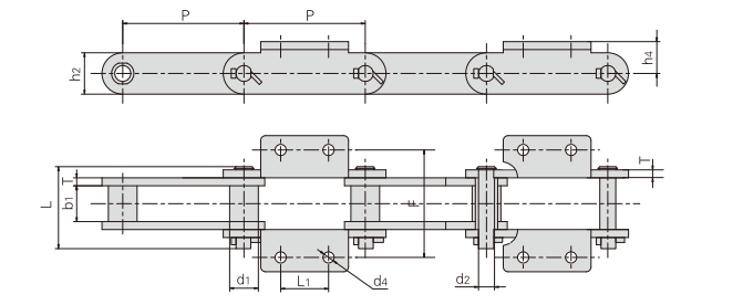
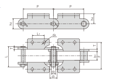
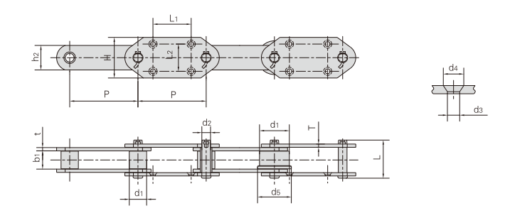
The tables are grouped by chain family, and within each family by the dimension set that matters for that group. Every table carries the pitch P and the tensile strength Q; the remaining columns describe the geometry a plant needs in order to check that the chain will fit the elevator it is going into.
Pitch, P. The centre distance between adjacent pins, in millimetres. Pitch is the first thing to match, because the sprocket or chain wheel is cut to it and a chain of the wrong pitch cannot be run on it.
Tensile strength, Q min. Given in kN with the equivalent in lbf. This is the figure to compare against the total chain tension on the elevator - the sum of the bucket load, the chain's own weight and the pull needed to move both. Where a table also gives an average tensile strength Q0, that is a higher reference value and should not be used in place of Q min for sizing.
Roller or bush diameter, d1. For a roller chain this is the external roller diameter; for a bush chain, note that d1 is the external diameter of the bush. The two are not measured the same way, and the tables mark the bush-chain rows with an asterisk where the distinction applies.
Width between inner plates, b1. The clear space between the inner plates, which sets how wide a bucket attachment or a chain-wheel groove can be.
Pin diameter d2 and pin length L. Pin diameter sets the bearing area in the joint and therefore the wear rate under load; pin length has to clear the attachment plates and the chain-wheel width.
Plate depth h2 and plate thickness T. Plate depth is the height of the sidebar and governs the chain's resistance to bending; thickness is the sidebar gauge and appears in the tables as a single figure or as a pair such as 8.0/6.3 where the inner and outer plates differ.
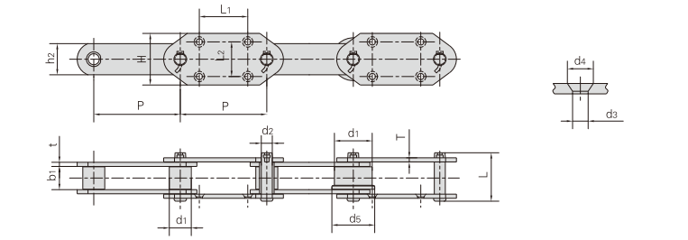
Attachment dimensions. The remaining columns describe the plate or fitting that carries the bucket - overall height H, lengths L1 and L2, widths F and W, and hole diameters d3 and d4. The final set of tables covers the attachment plates themselves, including the K-series plates used on the central lifting chain.
Where a cell shows a dash, that dimension does not apply to the chain in that row - usually because the chain has no second roller diameter or no second attachment length. A dash is not a missing value to be filled in.
Operating Conditions and Material Selection
Abrasion is the governing condition. The chain sees a continuous supply of hard, fine material. Everything that protects the joint - the sealing arrangement, the hardness at the pin and bush, the cleanliness of the lubricant that remains inside the seal - is aimed at that one problem.
Temperature rises along the process. Raw-material handling is close to ambient; clinker comes off the cooler hot, and the chain that carries it works in a raised-temperature zone. Where a chain serves the clinker side, the temperature at the chain is part of the selection, not an afterthought.
The duty is continuous. A cement plant elevator runs the shift, the week and usually the campaign. That is why the service-life figure that matters here is measured in years of continuous running, and why a chain that is marginally cheaper but wears faster is not a saving.
Load is uneven. Buckets are loaded in batches rather than uniformly, so the chain sees a cyclic tension superimposed on the steady pull. Joints fail from the accumulation of that cycling rather than from a single overload, which is another reason the joint - not the plate - is where these chains are lost.
One practical point on selection. The tables give a wide range of chain numbers for a reason: a plant should match the chain to the elevator it already has rather than the other way round. Where the existing chain is known by its number, that number is the fastest way to the right row; where it is not, the pitch and the attachment dimensions measured off the worn chain will identify it.
Selection Guidance
Start from the elevator type where one is known. The elevator-type table maps chain numbers to NE15, NE30, NE50, NE100, NE150, NE200, NE300 and NE400 machines, which is the quickest route from a machine size to a chain number for an NE installation.
Then check the two figures that decide it. Pitch has to match the existing sprocket or chain wheel, and tensile strength has to exceed the total chain tension with margin. Everything else in the table is geometry that has to fit rather than a figure to optimise.
Choose the attachment by what it carries. G4 plates are the standard attachment on the NE and NSE bucket elevator chains. The central lifting chain uses K443, K4, K3 and similar auxiliary plates, and the attachment tables at the end of this page give the dimensions for K24, K3, K35, K44 and K443.
Where the duty is shared, split it. A plant running both a raw-material elevator and a clinker elevator is often better served by two chain numbers than by one - the clinker side needs the temperature and abrasion allowance, and putting the heavier chain on the raw side only spends money.
Where the numbers do not resolve it, send a drawing. An existing chain, or a drawing of the attachment, settles the remaining questions faster than a table lookup. Non-standard pitch, attachment geometry and plate arrangements are all built to order.
Applications in Cement Plants
Raw material handling. Limestone, clay and corrected materials after crushing and grinding. Bucket elevators on the NE series with G4 attachments carry the material into the raw mill circuit and the blending silo.
Raw meal and kiln feed. Fine, free-flowing and highly abrasive. The conveyor chains with attachments listed at the start of the tables cover this duty alongside the bucket elevator chains.
Clinker handling. The hottest and most abrasive point in the plant. Clinker elevators are the reason the range runs up to the higher tensile figures and to the larger pitches.
Cement grinding and dispatch. Finished cement from the mill to the silos and to the packing plant, where the chain runs loaded continuously and the dust is at its finest.
Central lifting. Where the plant uses a single central lift rather than multiple elevators, the central lifting chain with K-series plates carries the load alone - which is why it is the heaviest family in the range and the one that goes to pitch 500 mm.
Ordering, Inspection and Service
An order for a cement chain is normally placed against the chain number rather than against a description, so the first step is to identify the existing chain or specify the new one from the tables on this page.
What to send. The chain number if it is known, or failing that the pitch, the tensile figure you need and the attachment dimensions. For a replacement, the elevator type and the number of metres or links required. For a new line or a non-standard attachment, the drawing.
Inspection on receipt. Check the pitch of the new chain against the sprocket or chain wheel, confirm the attachment dimensions against the drawing, and check that the sealing arrangement at the joint is intact on every link - the whole point of the design is that this seal is present and undamaged.
In service. The maintenance task that matters on this chain is watching for elongation, because elongation is the first sign that the seal has been breached and that abrasive material has reached the joint. Measure across a fixed number of pitches at intervals and record the readings, so that wear rate can be read from the record rather than estimated.
Replacement. A chain is normally replaced when elongation reaches the limit the elevator manufacturer sets, not when it breaks. Because the chain number identifies the whole assembly, a replacement does not require re-measuring the installation.
FAQ
Q1: What is the pitch range of these chains?
A: From 75 mm to 500 mm across the range. The bucket elevator chains run from P75 to P350, and the heavy central lifting chains go to P500.
Q2: What tensile strength is available?
A: From 30 kN on the smallest chain numbers to 2,650 kN on the largest. The elevator-type table maps the individual chain numbers to their tensile figures, and the attachment tables carry the same figures for the relevant rows.
Q3: What is the difference between the NE and NSE chains?
A: The NE series chain is used for cement raw materials and rough-machined raw materials; the NSE series for cement clinker and cement products. Both use the G4 attachment plate. The NSE duty is generally the hotter and more abrasive of the two.
Q4: What is the G4 attachment plate?
A: G4 is the standard attachment plate fitted to the NE and NSE bucket elevator chains, and the code appears in the chain number itself on the rows that carry it.
Q5: What are the K443, K4 and K3 plates?
A: They are the auxiliary attachment plates used with the central lifting chain. The final table on this page gives the dimensions for K24, K3, K35, K44 and K443 - for chain numbers 856, 857, 859, 864, S859F1-K4, S984F3-K443 and S864F3-K443.
Q6: What is meant by the patented sealing structure?
A: The joint carries its own sealing arrangement rather than relying only on the fit between pin and bush. It is designed to keep abrasive cement dust out of the bearing surface, which is what limits wear, holds running accuracy and extends the interval between replacements.
Q7: Can I order against a sample or a drawing?
A: Yes. Non-standard pitch, attachment geometry and plate arrangements are built to order. A drawing or a sample chain is normally the fastest way to match a chain that is not identified on this page.
Q8: How do I choose between the chain numbers?
A: Match the pitch to the existing sprocket or chain wheel, then check that the tensile figure exceeds the total chain tension on the elevator. The elevator-type table is the quickest route where the machine size is known.
Q9: What does a dash in the table mean?
A: That the dimension does not apply to that chain number - for example a second roller diameter or a second attachment length on a chain that has only one. It does not indicate a value we have omitted.
Q10: Do you support chain identification from a worn chain?
A: Yes. Send the pitch measured across several pitches, the attachment dimensions and the chain number if any is legible. That combination identifies most cement chains.
Send us the chain number, the pitch or the attachment drawing.
A worn chain identifies itself from its pitch and attachment dimensions, and a drawing or a sample is enough for us to match a non-standard plate.
Hot Tags: conveying chain for cement industry, China conveying chain for cement industry manufacturers, suppliers, factory, Automobile Production Line Chains, Bottle Washer Conveyor Chains, chain, Conveyor Chains For Steel Mill, Steel Sleeve Chain For Engineering, Sugar Machine Chains
Conveyor Chain with Attachments
The first two tables cover the conveyor chains with attachments used across cement handling, identified by conveyor type and chain number. DS400 and DS640 are the two standard conveyor types in the group; the P160F rows marked with an asterisk are bush chains, where d1 in the table is the external diameter of the bush rather than a roller diameter.
The SDB group follows the same column structure at pitch 250 mm, with SDB400, SDB500 (540) and SDB630 (600) covering the three sizes.
| Conveyor type |
Chain No. | Pitch | Roller diameter |
Width between inner plates |
Pin diameter |
Pin length |
Plate depth |
Plate thickness |
Attachment dimension |
Tensile strength |
|||
| P | d1 | b1 | d2 | L | h2 | T | L1 | F | h4 | d4 | Q min |
||
| mm | mm | mm | mm | mm | mm | mm | mm | mm | mm | mm | kN/lbf | ||
| DS400 | P152F123 | 152.4 | 36.0 | 36.5 | 15.5 | 90.0 | 50.0 | 8.0 | 60 | 120 | 38 | 14 | 275/61863 |
| DS640 | P250F44 | 250.0 | 48.5 | 57.6 | 22.2 | 120.0 | 75.0 | 10.0 | 125 | 160 | 60 | 12 | 560/125976 |
| *P160F76K2 | 160.0 | 40.0 | 66.0 | 26.0 | 128.0 | 70.0 | 10.0 | 120 | 175 | 43 | 15 | 450/101164 | |
| *P160F82K2 | 160.0 | 36.0 | 65.0 | 20.0 | 108.0 | 60.0 | 9.0 | 60 | 130 | 45 | 14 | 300/67443 | |
| P160F99K2 | 160.0 | 50.0 | 55.0 | 20.0 | 108.0 | 60.0 | 9.0 | 60 | 130 | 65 | 17 | 300/67443 | |
| *Bush chain:d1 in the table indicates the external diameter of the bush. | |||||||||||||
| Conveyor type |
Chain No. | Pitch | Roller diameter |
Width between inner plates |
Pin diameter |
Pin length |
Plate depth |
Plate thickness |
Attachment dimension |
Tensile strength |
|||
| P | d1 | b1 | d2 | L | h2 | T | L1 | F | h4 | d4 | Q min |
||
| mm | mm | mm | mm | mm | mm | mm | mm | mm | mm | mm | kN/lbf | ||
| SDB400 | P250F45 | 250.0 | 36.0 | 40.0 | 20.0 | 89.0 | 65.0 | 8.0 | 85 | 130 | 55 | 14.0 | 450/101230 |
| SDB500 (540) |
P250F46 | 250.0 | 36.0 | 44.0 | 21.0 | 94.0 | 85.0 | 8.0 | 85 | 132 | 55 | 18.5 | 500/112479 |
| SDB630 (600) |
P250F47 | 250.0 | 45.0 | 52.0 | 30.0 | 128.0 | 115.0 | 10.0 | 85 | 162 | 75 | 18.5 | 1000/224957 |
Conveyor Chains for Bucket Elevators
The bucket elevator chains are listed by chain number rather than by machine, because one chain number can serve more than one elevator size. This table covers pitch P95 through P350F2-G4, with the breaking tensile figure alongside the average value.
The second table below repeats the same chain numbers with the attachment geometry - H, L1, L2, d3 and d4 - so a chain can be checked for fit without leaving this section.
| Chain No. | Pitch | Roller diameter |
Width between inner plates |
Pin diameter |
Pin length |
Plate depth |
Plate thickness |
Tensile strength |
Average tensile trength |
Weight per meter |
|
| P | d1 max |
d5 | b1 min |
d2 max |
L max |
h2 max |
t/T max |
Q min |
Q0 | q | |
| mm | mm | mm | mm | mm | mm | mm | mm | kN/lbf | kN | kg/m | |
| P95 | 95.0 | 50.8 | 58.0 | 30.0 | 13.50 | 70.0 | 38.0 | 6.0 | 75.0/16871 | 82.5 | 9.93 |
| P100F225-G4 | 100.0 | 40.0 | - | 22.0 | 11.30 | 53.5 | 32.0 | 4.5 | 69.0/15511 | 75.9 | 5.00 |
| P100F269-G4 | 100.0 | 48.5 | - | 57.6 | 25.40 | 120.0 | 75.0 | 10.0 | 550.0/123640 | 605.0 | 31.10 |
| P125F61-G4 | 125.0 | 63.5 | - | 67.4 | 32.00 | 141.0 | 90.0 | 12.0 | 750.0/168600 | 825.0 | 47.00 |
| P125F62-G4 | 125.0 | 70.0 | - | 75.0 | 36.00 | 168.0 | 100.0 | 16.0 | 1000.0/224800 | 1100.0 | 68.60 |
| P150F142-G4 | 150.0 | 78.0 | - | 80.0 | 39.00 | 172.0 | 120.0 | 16.0 | 1350.0/303480 | 1485.0 | 78.90 |
| RF10150RF1 | 150.0 | 50.0 | 60.0 | 30.0 | 14.50 | 69.0 | 38.1 | 8.0/6.3 | 200.0/44992 | 220.0 | 8.64 |
| P150F47 | 150.0 | 54.0 | - | 40.0 | 27.00 | 112.0 | 68.5 | 12.0 | 600.0/67487 | 680.0 | 25.70 |
| RF10150RF1-G4 | 150.0 | 29.0 | - | 30.0 | 14.50 | 69.0 | 38.1 | 6.3 | 200.0/44960 | 220.0 | 16.70 |
| P152F41 | 152.4 | 38.1 | - | 36.0 | 15.50 | 90.0 | 50.0 | 8.0 | 150.0/33743 | 165.0 | 11.91 |
| P152F236-G4 | 152.4 | 36.0 | - | 36.5 | 18.00 | 87.0 | 50.0 | 8.0 | 280.0/62944 | 308.0 | 12.10 |
| RF17200MF1-G-4 | 200.0 | 44.5 | - | 51.4 | 19.10 | 120.0 | 60.0 | 10.0 | 245.0/55114 | 269.5 | 17.60 |
| RF17200MF2-G-4 | 200.0 | 44.5 | - | 51.4 | 19.10 | 109.5 | 50.8 | 9.5 | 213.0/47916 | 243.0 | 15.10 |
| P200F128-G4 | 200.0 | 50.8 | - | 56.6 | 24.00 | 120.0 | 70.0 | 9.5 | 450.0/101164 | 490.0 | 19.40 |
| P200F130-G4 | 200.0 | 44.5 | - | 51.8 | 19.10 | 113.0 | 60.0 | 10.0 | 321.0/72164 | 353.1 | 17.80 |
| P250F6 | 250.0 | 63.5 | - | 67.0 | 31.80 | 146.0 | 90.0 | 12.0 | 900.0/101230 | 495.0 | 31.70 |
| P250F66 | 250.0 | 80.0 | - | 51.4 | 19.10 | 109.5 | 50.8 | 9.5 | 329.0/73962 | 378.0 | 19.79 |
| P250F71SS | 250.0 | 100.0 | 125.0 | 79.0 | 22.00 | 120.0 | 64.0 | 10.0 | 320.0/71939 | 368.0 | 29.80 |
| P250F87-G4 | 250.0 | 80.0 | - | 51.4 | 22.00 | 109.0 | 50.8 | 9.5 | 329.0/73959 | 361.9 | 19.60 |
| P250F110-G4 | 250.0 | 80.0 | 105.0 | 51.5 | 19.10 | 110.0 | 50.0 | 9.0 | 356.4/80119 | 392.0 | 18.30 |
| P 250F163 | 250.0 | 70.0 | - | 76.0 | 35.00 | 165.0 | 100.0 | 16.0 | 1100.0/247280 | 1210.0 | 44.10 |
| P300F1 | 300.0 | 70.0 | - | 75.0 | 35.00 | 174.0 | 100.0 | 16.0 | 1065.0/239580 | 1118.0 | 47.47 |
| P350F2-G4 | 350.0 | 85.0 | - | 85.0 | 41.75 | 189.5 | 115.0 | 16.0 | 1200.0/269772 | 1372.0 | 48.43 |
| Chain No. | P | H | L1 | L2 | d3 | d4 |
| mm | mm | mm | mm | mm | mm | |
| P95 | 95.0 | 95.0 | 50.0 | 70.0 | 12.0 | 21.0 |
| P100F225-G4 | 100.0 | 80.0 | 50.0 | 50.0 | 10.0 | 15.0 |
| P100F269-G4 | 100.0 | 75.0 | 100.0 | 106.0 | 18.0 | 30.0 |
| P125F61-G4 | 125.0 | 180.0 | 125.0 | 130.0 | 18.0 | 33.0 |
| P125F62-G4 | 125.0 | 180.0 | 125.0 | 130.0 | 18.0 | 33.0 |
| RF10150RF1 | 150.0 | 100.0 | 75.0 | 70.0 | 11.0 | 20.0 |
| P150F47 | 150.0 | 110.0 | 75.0 | 75.0 | 12.0 | 22.0 |
| P150F142-G4 | 150.0 | 120.0 | 150.0 | 170.0 | 22.0 | 38.0 |
| RF10150RF1-G4 | 150.0 | 110.0 | 75.0 | 70.0 | 11.0 | 20.0 |
| P152F41 | 152.4 | 110.0 | 75.0 | 70.0 | 14.5 | 25.0 |
| P152F236-G4 | 152.4 | 1100 | 75.0 | 70.0 | 14.0 | 27.0 |
| RF17200MF1-G-4 | 200.0 | 125.0 | 100.0 | 80.0 | 18.0 | 33.0 |
| RF17200MF2-G-4 | 200.0 | 120.0 | 100.0 | 80.0 | 15.0 | 26.0 |
| P200F128-G4 | 200.0 | 130.0 | 100.0 | 80.0 | 18.0 | 31.0 |
| P200F130-G4 | 200.0 | 125.0 | 100.0 | 80.0 | 18.0 | 30.0 |
| P250F6 | 250.0 | 150.0 | 140.0 | 100.0 | 17.7 | 30.0 |
| P250F66 | 250.0 | 150.0 | 140.0 | 100.0 | 15.0 | 26.0 |
| P250F71SS | 250.0 | 150.0 | 110.0 | 100.0 | 18.0 | - |
| P250F87-G4 | 250.0 | 150.0 | 140.0 | 100.0 | 15.0 | 26.0 |
| P250F110-G4 | 250.0 | 125.0 | 150.0 | 80.0 | 14.0 | 27.0 |
| P250F163 | 250.0 | 1510 | 140.0 | 100.0 | 18.0 | 30.0 |
| P300F1 | 300.0 | 180.0 | 170.0 | 120.0 | 22.0 | 39.0 |
| P350F2-G4 | 350.0 | 210.0 | 225.0 | 140.0 | 26.0 | 42.2 |
Matching Chain Numbers to Elevator Types
Where the machine size is known, this is the table to start from. It maps chain numbers to NE15, NE30, NE50, NE100, NE150, NE200, NE300 and NE400 elevators, with the pitch, plate thickness and attachment dimensions alongside.
Two chain numbers are listed under NE150, and the two P100F rows at the top carry no elevator type because they are specified by chain number alone.
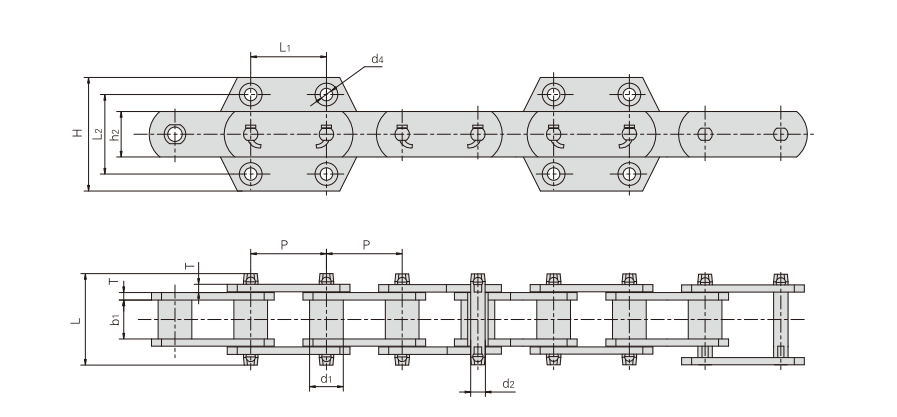
| Elevator type |
Chain No. | Pitch | Roller diameter |
Width between inner plates |
Pin diameter |
Pin length |
Plate depth |
Plate thickness |
Attachment dimension |
Tensile strength |
|||
| P | d1 | b1 | d2 | L | h2 | T | H | L1 | L2 | d4 | Q min |
||
| mm | mm | mm | mm | mm | mm | mm | mm | mm | mm | mm | kN/lbf | ||
| P100F112.04 | 100.0 | 44.5 | 52.0 | 19.30 | 120.0 | 60.0 | 10.0 | 150 | 100 | 105 | 18.5 | 350.0/78735 | |
| P100F107.04 | 100.0 | 50.8 | 58.0 | 25.40 | 120.0 | 75.0 | 10.0 | 150 | 100 | 105 | 18.5 | 550.0/123726 | |
| NE15 | P101.6F92 | 101.6 | 26.5 | 27.0 | 11.50 | 70.0 | 35.0 | 6.0 | - | 40 | 90 | 12.0 | 100.0/22495 |
| NE30 | P152F119 | 152.4 | 36.0 | 36.5 | 15.50 | 90.0 | 50.0 | 8.0 | - | 60 | 120 | 14.0 | 240.0/53990 |
| NE50 | P152F120 | 152.4 | 36.0 | 36.5 | 15.50 | 90.0 | 50.0 | 8.0 | 110 | 75 | 70 | 14.0 | 240.0/53990 |
| P152F126 | 152.4 | 34.9 | 37.1 | 15.80 | 88.0 | 44.5 | 7.9 | 110 | 75 | 70 | 15.0 | 186.2/41887 | |
| NE100 | P200F64 | 200.0 | 44.5 | 51.8 | 19.10 | 120.0 | 60.0 | 10.0 | 125 | 100 | 80 | 18.0 | 380.0/85484 |
| NE150 | P200F65 | 200.0 | 48.5 | 57.6 | 22.20 | 120.0 | 75.0 | 10.0 | 125 | 100 | 80 | 18.0 | 550.0/123727 |
| P200F63 | 200.0 | 48.5 | 57.6 | 22.20 | 125.0 | 75.0 | 10.0 | 125 | 100 | 80 | 18.5 | 315.0/70861 | |
| NE200 | P250F42 | 250.0 | 63.5 | 67.4 | 31.75 | 143.0 | 90.0 | 12.0 | 150 | 140 | 100 | 18.0 | 750.0/168718 |
| NE300 | P250F43 | 250.0 | 63.5 | 67.4 | 31.75 | 146.0 | 90.0 | 12.0 | 150 | 140 | 100 | 18.0 | 750.0/168718 |
| NE400 | P300F9 | 300.0 | 70.0 | 75.0 | 35.00 | 170.0 | 100.0 | 16.0 | 180 | 170 | 125 | 22.0 | 1065.0/239580 |
Elevator Chain Attachment Dimensions
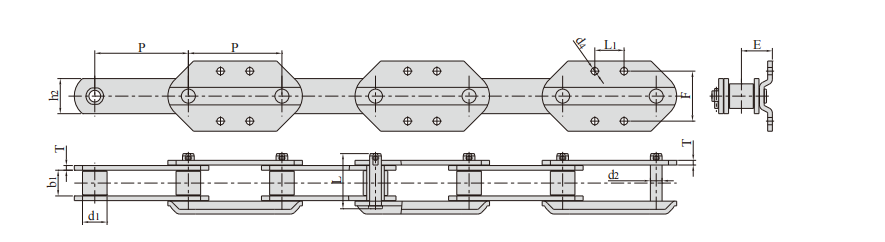
This table gives the attachment geometry for the elevator chain numbers from P75F18 to P150F97-G4, including the F, L1, d4 and E dimensions that position the bucket relative to the chain.
Pitch ranges from 75 mm to 150 mm, so this group covers the lighter end of the elevator range where the attachment interface changes most between chain numbers.
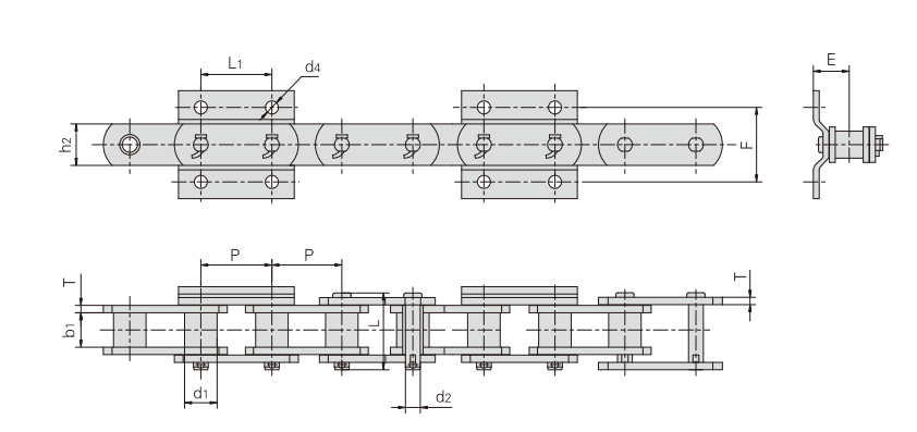
| Chain No. | Pitch | Roller diameter |
Width between inner plates |
Pin diameter |
Pin length |
Plate depth |
Plate thickness |
Attachment dimension |
Tensile strength |
|||
| P | d1 max |
b1 min |
d2 | L | h2 | T | F | L1 | d4 | E | Q min |
|
| mm | mm | mm | mm | mm | mm | mm | mm | mm | mm | mm | kN/lbf | |
| P75F18 | 75.0 | 29.0 | 30.0 | 14.5 | 69.0 | 38.1 | 6.3 | 80.0 | 75.0 | 14.0 | 38.5 | 204.9/46094 |
| P75F22 | 75.0 | 32.0 | 37.1 | 15.9 | 86.5 | 44.5 | 7.9 | 75.0 | 75.0 | 14.0 | 46.5 | 253.6/57049 |
| P75F24 | 75.0 | 29.0 | 30.0 | 14.5 | 69.0 | 38.1 | 6.3 | 80.0 | 75.0 | 14.0 | 38.5 | 204.9/46093 |
| P75F41-G4 | 75.0 | 29.0 | 29.4 | 14.5 | 69.0 | 38.1 | 6.3 | 80.0 | 75.0 | 14.0 | 68.5 | 205.0/46084 |
| P75F48-G4 | 75.0 | 29.0 | 30.0 | 14.5 | 69.0 | 38.1 | 6.3 | 80.0 | 75.0 | 14.0 | 38.5 | 205.0/46084 |
| P75F59-G4 | 75.0 | 29.0 | 30.0 | 14.5 | 69.0 | 38.1 | 6.3 | 80.0 | 75.0 | 14.0 | 38.5 | 205.0/46084 |
| M224F36-S-75 | 75.0 | 42.0 | 47.0 | 21.0 | 97.0 | 56.0 | 8.0 | 100.0 | 75.0 | 18.0 | 55.0 | 224.0/50909 |
| P76.2F31 | 76.2 | 34.9 | 37.1 | 17.0 | 86.5 | 44.5 | 7.9 | 80.0 | 75.0 | 14.0 | 46.5 | 253.6/57009 |
| P76.2F51-G4 | 76.2 | 35.0 | 37.0 | 18.0 | 86.5 | 50.0 | 8.0 | 80.0 | 75.0 | 14.0 | 43.5 | 290.0/65192 |
| P76.2F55-G4 | 76.2 | 34.9 | 37.1 | 15.9 | 84.6 | 44.5 | 7.9 | 80.0 | 75.0 | 14.0 | 46.5 | 253.6/57009 |
| P76.2F81-G4 | 76.2 | 35.0 | 37.0 | 18.0 | 94.0 | 45.0 | 10.0 | 80.0 | 75.0 | 14.0 | 46.0 | 342.0/76882 |
| P100F97 | 100.0 | 40.1 | 51.4 | 19.1 | 109.5 | 50.8 | 9.5 | 100.0 | 100.0 | 16.0 | 58.0 | 351.0/78960 |
| P100F127-G4 | 100.0 | 50.0 | 57.5 | 24.0 | 117.0 | 63.5 | 9.5 | 100.0 | 100.0 | 16.0 | 62.5 | 470.0/105730 |
| P100F371-G4 | 100.0 | 40.0 | 51.5 | 20.0 | 111.5 | 55.0 | 10.0 | 100.0 | 100.0 | 16.0 | 55.0 | 420.0/94416 |
| P125F41 | 125.0 | 57.0 | 67.0 | 28.0 | 147.0 | 76.0 | 12.5 | 110.0 | 125.0 | 18.0 | 77.0 | 690.0/155112 |
| P125F47-G4 | 125.0 | 60.0 | 67.0 | 36.0 | 142.0 | 90.0 | 12.0 | 110.0 | 125.0 | 19.0 | 70.6 | 613.0/137802 |
| P150F97-G4 | 150.0 | 35.0 | 37.0 | 18.0 | 86.5 | 50.0 | 8.0 | 80.0 | 75.0 | 14.0 | 43.0 | 280.0/62944 |
Heavy-Duty Pitch Chains
Two chain numbers at the top of the pitch range, both specified where a single chain carries a large load at a large pitch. P315F12 and P500F4 are the largest pitches on this page.
Note the roller diameters: 120 mm and 150 mm respectively, against 26.5 mm to 85 mm on the standard elevator chains. The roller and pin sizes are what separate this group from the rest of the range.
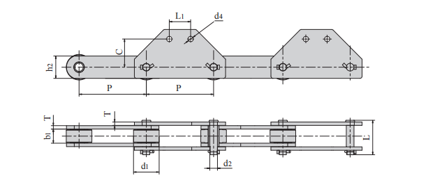
| Chain No. | Pitch | Roller diameter |
Width between inner plates |
Pin diameter |
Pin length |
Plate depth |
Plate thickness |
Attachment dimension |
Tensile strength |
||
| P | d1 max |
b1 min |
d2 | L | h2 | T | L1 | C | d4 | Q min |
|
| mm | mm | mm | mm | mm | mm | mm | mm | mm | mm | kN/lbf | |
| P315F12 | 315.0 | 120.0 | 66.5 | 36.0 | 162.0 | 105.0 | 16.0 | 100.0 | 133.0 | 25.0 | 1000/224958 |
| P500F4 | 500.0 | 150.0 | 120.0 | 50.0 | 227.0 | 130.0 | 20.0 | 400.0 | 120.0 | 26.0 | 2650/596138 |
Bush Chains
The bush chain group covers P152F172, P152F193K2 and P152F201K4. As with the bush chains earlier on this page, d1 is the external diameter of the bush rather than a roller diameter.
The second table gives the attachment dimensions for the same three chain numbers - h4, h5, F1, F2, W, L1, L2 and the hole diameters d4, d5 and d6 - which is the set needed when the attachment is designed rather than matched.
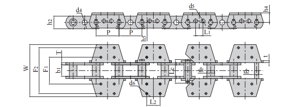
| Chain No. | Pitch | Bush diameter |
Width between inner plates |
Pin diameter |
Pin length |
Inner Plate depth |
Plate thickness |
Tensile strength |
Average tensile strength |
Weigth per meter |
| P | d1 max |
b1 min |
d2 max |
Lc max |
h max |
t/T | Q min |
Qo | q | |
| mm | mm | mm | mm | mm | mm | mm | kN/lbf | kN | kg /m | |
| P152F172 | 152.4 | 50.8 | 76.2 | 28.6 | 157.5 | 83.60 | 14.2/12.7 | 431.0/96889 | 474.1 | 47.7 |
| P152F193K2 | 152.4 | 44.5 | 76.2 | 25.4 | 152.0 | 76.20 | 12.7/12.7 | 431.0/96889 | 474.1 | 35.3 |
| P152F201K4 | 152.4 | 44.5 | 76.2 | 25.4 | 152.0 | 82.55 | 12.7/12.7 | 431.0/96889 | 474.1 | 44.5 |
| Chain No. | P | h4 | h5 | F1 | F2 | W | L1 | L2 | d4 | d5 | d6 |
| mm | mm | mm | mm | mm | mm | mm | mm | mm | mm | mm | |
| P152F172 | 152.4 | 63.50 | 10.0 | 178.0 | 305.0 | 347.0 | 48.8 | 88.9 | 25.0 | 25.0 | 14.2 |
| P152F193K2 | 152.4 | 47.75 | 10.0 | 184.0 | - | 241.0 | 48.8 | 63.5 | 34.0 | 25.0 | 17.5 |
| P152F201K4 | 152.4 | 63.50 | - | 177.8 | 304.8 | 355.6 | - | 88.9 | - | - | 14.3 |
Chains with G4 Attachments
These four chain numbers carry the G4 attachment plate: P160F61-G4, P200F95-G4, P200F153-G4 and RF17200S-G4. The G4 code is part of the chain number, so it identifies the attachment as well as the chain.
P200F95-G4 and P200F153-G4 share the same chain dimensions and differ in the attachment, which is why their rows read identically in this table.
| Chain No. | Pitch | Roller diameter |
Width between inner plates |
Pin diameter |
Pin length |
Plate depth |
Plate thickness |
Attachment dimension |
Tensile strength |
|||
| P | d1 max |
b1 min |
d2 | L | h | T | F | L1 | d4 | E | Q min |
|
| mm | mm | mm | mm | mm | mm | mm | mm | mm | mm | mm | kN/lbf | |
| P160F61-G4 | 160.0 | 42.0 | 44.0 | 20.0 | 94.3 | 60.00 | 8.0 | 85.5 | 50.0 | 12.5 | 53.0 | 250.0/56202 |
| P200F95-G4 | 200.0 | 34.9 | 37.1 | 15.9 | 86.4 | 44.45 | 7.9 | 100.0 | 100.0 | 15.0 | 45.0 | 280.0/62947 |
| P200F153-G4 | 200.0 | 34.9 | 37.1 | 15.9 | 86.4 | 44.45 | 7.9 | 100.0 | 100.0 | 15.0 | 45.0 | 280.0/62947 |
| RF17200S-G4 | 200.0 | 40.1 | 51.4 | 19.1 | 109.5 | 50.80 | 9.5 | 100.0 | 100.0 | 15.0 | 65.0 | 360.0/80931 |
Further Pitch and Attachment Options
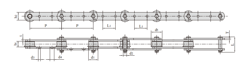
Two further chain numbers at pitch 75 mm and 200 mm, with a second roller diameter d5 and a third attachment dimension d3 alongside the standard columns.
The lighter of the two, P75F39-G2, runs at 2.80 kg/m, against 13.52 kg/m for P200F70. Weight per metre in this table is a useful cross-check when comparing a proposed chain against the drive capacity of an existing elevator.
| Chain No. | Pitch | Roller diameter |
Width between inner plates |
Pin diameter |
Pin length |
Plate depth |
Plate thickness |
Attachment dimension |
Tensile strength |
Weight per meter |
|||
| P | d1 max |
d5 max |
b1 min |
d2 max |
L max |
h2 max |
t/T max |
L1 max |
d3 max |
d4 max |
Q min |
q | |
| mm | mm | mm | mm | mm | mm | mm | mm | mm | mm | mm | kN/lbf | kg/m | |
| P75F39-G2 | 75.0 | 31.8 | - | 16.0 | 8.0 | 41.0 | 22.0 | 3.2 | 30.0 | 8.0 | 13.5 | 30/6744 | 2.80 |
| P200F70 | 200.0 | 60.0 | 70.0 | 35.0 | 22.0 | 98.0 | 50.0 | 9.5 | 80.0 | 14.0 | 27.0 | 320/71940 | 13.52 |
Central Lifting Chain and Attachment Plates
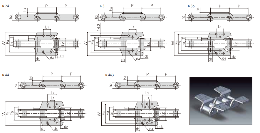
The central lifting chain group is the heaviest on this page. Chain numbers 856, 857, 859, 864, S859F1-K4, S984F3-K443 and S864F3-K443 cover pitch 152.4 mm and 177.8 mm with tensile figures from 539 kN to 1,230 kN.
The final table gives the attachment plates for this group: K24, K3, K35, K44 and K443, with the plate dimensions and the weight of each attachment. Note that chain 856 appears three times against three different plates, so the chain number alone does not identify the attachment on this family.
| Chain No. | Pitch | Bush diameter |
Width between inner plates |
Pin diameter |
Pin length |
Plate depth |
Plate thickness |
Tensile strength |
Average tensile strength |
Weight per meter |
| P | d1 max |
b1 min |
d2 max |
L max |
h max |
t/T | Q min |
Qo | ||
| mm | mm | mm | mm | mm | mm | mm | kN/lbf | kN | kg/m | |
| 856 | 152.4 | 44.5 | 76.2 | 25.40 | 155.5 | 63.5 | 12.7 | 539/121252 | 592.9 | 24.5 |
| 857 | 152.4 | 44.5 | 76.2 | 25.40 | 155.5 | 82.6 | 12.7 | 775/174342 | 852.5 | 30.0 |
| 859 | 152.4 | 60.3 | 95.3 | 31.75 | 190.0 | 101.6 | 16.0 | 1180/265450 | 1298.0 | 51.0 |
| 864 | 177.8 | 60.3 | 95.3 | 31.75 | 190.0 | 101.6 | 16.0 | 1230/276698 | 1353.0 | 51.0 |
| S859F1-K4 | 152.4 | 60.4 | 95.3 | 31.75 | 189.5 | 101.6 | 16.0 | 690.0/155112 | 759.0 | 73.8 |
| S984F3-K443 | 177.8 | 63.5 | 95.3 | 35.00 | 204.0 | 101.6 | 16.0 | 689.4/154977 | 758.3 | 74.0 |
| S864F3-K443 | 177.8 | 60.4 | 95.3 | 31.75 | 189.5 | 101.6 | 16.0 | 1045.0/234916 | 1149.5 | 69.8 |
| Chain No. | Attachment type |
Attachment dimension |
Weight per att |
||||||||
| P | h4 | Fb | Fa | W | L1 | L2 | T | d4 | |||
| mm | mm | mm | mm | mm | mm | mm | mm | mm | kg/att. | ||
| 856 | K24 | 152.4 | 47.6 | - | 184.2 | 241 | 63.5 | - | 12.7 | 18.0 | 1.5 |
| 856 | K3 | 152.4 | 47.6 | 166.7 | 277.8 | 344 | 70.0 | - | 12.7 | 15.0 | 2.8 |
| 856 | K35 | 152.4 | 47.6 | 184.2 | 298.5 | 344 | 63.5 | - | 12.7 | 18.0 | 2.8 |
| 859 | K44 | 152.4 | 76.2 | 228.6 | 330.2 | 381 | 70.0 | 114.5 | 16.0 | 17.5 | 5.0 |
| 864 | K443 | 177.8 | 76.2 | 228.6 | 330.2 | 381 | 95.3 | 140.0 | 16.0 | 17.5 | 7.5 |
| S859F1-K4 | K44 | 152.4 | 76.2 | 228.6 | 330.2 | 381 | 69.9 | 114.3 | 16.0 | 17.5 | 5.5 |
| S984F3-K443 | K443 | 177.8 | 76.2 | 228.6 | 330.2 | 378 | 95.3 | 139.7 | 16.0 | 17.5 | 6.4 |
| S864F3-K443 | K443 | 177.8 | 76.2 | 228.6 | 330.2 | 381 | 95.3 | 139.7 | 16.0 | 17.5 | 6.2 |


