



Hangzhou Ocean Industry Co., Ltd. is one of the leading manufacturers and suppliers of other(drive chains) in China. Welcome to wholesale bulk durable industrial chains and power transmission parts made in China here from our factory. All customized products are with high quality and competitive price.
Other Drive Chains Manufacturer - Anti-Backbend, Side Bow, P.I.V., Coupling and Bush Chains for Special Drives | Ocean Industry
Drive chain is a broad word, and the six groups on this page are the families that sit outside ordinary transmission practice. An anti-backbend chain is allowed to bend in one direction only, which is what lets it push a load instead of merely pulling it. A side bow chain is allowed to bend sideways. A self-tooth-forming chain carries its own teeth. A chain coupling joins two shafts with a short length of duplex chain. A bush chain puts the load on a bush rather than on a roller. Every one of them is chosen against a drawing rather than from a catalogue page, which is how Ocean has worked since 2001: send the drawing, the worn chain, or the number stamped on the link and the geometry comes back to you for approval.

Anti-Backbend Chains for Pushing Windows
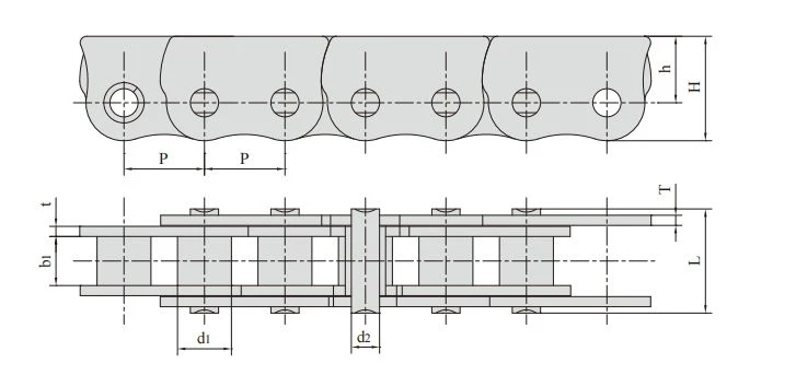
The link plates of an anti-backbend chain are shaped so that the chain articulates in one direction and locks in the other. That single restriction is the whole point of the design: it turns the chain into a pushing element, so a sash, hatch or vent can be driven away from the gearbox instead of being dragged toward it. Ten size families are listed below, from the 06BF34 at 9.525 mm pitch up to the 16AF101 at 25.400 mm pitch, in roller, bush and attachment builds. The number after the F is the attachment type, not a size, so an F10 chain and an F12 chain can share the same pitch and still carry completely different brackets.
Anti-backbend bush chain, 06BF to 16AF series (9.525 mm to 25.400 mm pitch)
| Chain No. | Pitch | Roller diameter |
Width between inner plates |
Pin diameter |
Pin length |
Plate dimension |
Tensile strength |
Weight per meter |
||
| P | d1 max |
b1 min |
d2 max |
L max |
H max |
h | t/T max |
Q min |
q | |
| mm | mm | mm | mm | mm | mm | mm | mm | kN/lbf | kg/m | |
| 06BF34 | 9.525 | 6.35 | 3.80 | 3.28 | 10.00 | 12.38 | 7.88 | 1.04 | 7.0/1574 | 0.47 |
| *06CF22 | 9.525 | 5.08 | 4.77 | 3.58 | 11.60 | 12.86 | 8.38 | 1.30 | 7.9/1776 | 0.51 |
| *06CF30 | 9.525 | 5.08 | 4.77 | 3.58 | 13.90 | 13.05 | 8.55 | 2.03/1.25 | 7.9/1776 | 0.71 |
| *P9.525F1 | 9.525 | 5.08 | 4.77 | 3.58 | 11.60 | 13.00 | 8.55 | 1.30 | 7.9/1776 | 0.57 |
| 08BF6 | 12.700 | 7.95 | 7.85 | 3.96 | 16.60 | 17.00 | 11.00 | 1.50 | 13.8/3102 | 0.91 |
| 415BF4 | 12.700 | 7.75 | 4.88 | 4.09 | 16.40 | 17.00 | 11.00 | 1.3/3.1 | 12.0/2698 | 1.07 |
| P12.7F4 | 12.700 | 7.50 | 5.50 | 4.45 | 15.60 | 14.30 | 8.50 | 2.03 | 15.0/3372 | 0.99 |
| 08BF20 | 12.700 | 8.51 | 7.75 | 4.45 | 16.70 | 16.50 | 10.50 | 1.60 | 18.0/4046 | 1.04 |
| 08BF208 | 12.700 | 8.51 | 7.75 | 4.45 | 17.00 | 16.50 | 10.50 | 1.60 | 10.0/2248 | 1.06 |
| 16AF101 | 25.400 | 15.88 | 15.75 | 7.92 | 32.70 | 26.90 | 14.80 | 3.25 | 56.7/12746 | 3.45 |
| *Bush chain:d1 in the table indicates the external diameter of the bush | ||||||||||
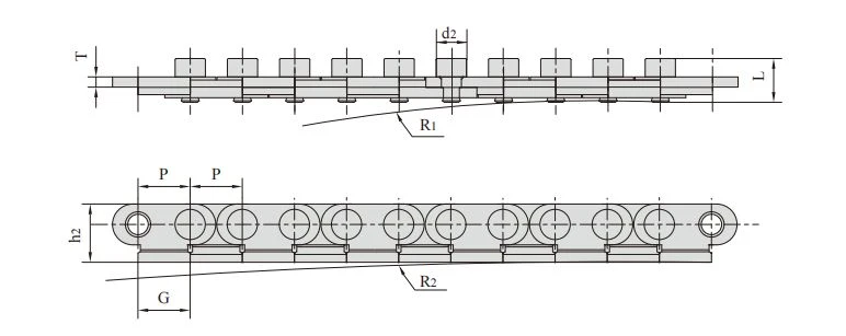
Chain with side bow radius, P12.75SB and P12.75SBF1 (12.75 mm pitch)
| Chain No. | Pitch | Pin diameter |
Pin length |
Plate dimension |
Side bow radius |
Weight per meter |
|||
| P | d2 max |
L max |
h2 max |
G max |
T max |
R1 | R2 | q | |
| mm | mm | mm | mm | mm | mm | mm | mm | kg/m | |
| P12.75SB | 12.75 | 7.4 | 10.65 | 14.25 | 12.8 | 2.5 | 500~800 | 1000 | 0.69 |
| P12.75SBF1 | 12.75 | 7.4 | 11.00 | 14.25 | 12.8 | 2.5 | 500~800 | 1000 | 1.08 |
Anti-backbend chain, P11.5 (11.5 mm pitch)

| Chain No. | Pitch | Width between inner plates |
Pin diameter |
Pin length |
Plate dimension |
Tensile strength |
|||
| P | b1 min |
d2 max |
d3 max |
L max |
H max |
h | T | Q min |
|
| mm | mm | mm | mm | mm | mm | mm | mm | kN/lbf | |
| P11.5 | 11.5 | 3.00 | 3.00 | 6.00 | 10.8 | 13.5 | 8.5 | 1.5 | 9.0/2023 |
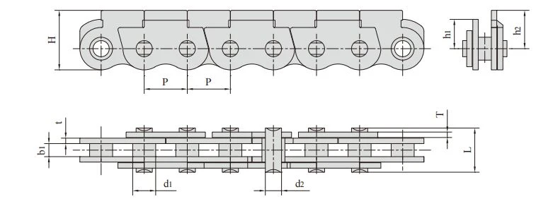
Anti-backbend bush chain, 06CF25SB and 06CF37SB (9.525 mm pitch)
| Chain No. | Pitch | Bush diameter |
Width between inner plates |
Pin diameter |
Pin length |
Plate dimension |
Tensile strength |
Weight per meter |
|||
| P | d1 max |
b1 min |
d2 max |
L max |
H max |
h1 | h2 | t/T | Q min |
q | |
| mm | mm | mm | mm | mm | mm | mm | mm | mm | kN/lbf | kg/m | |
| 06CF25SB | 9.525 | 5.08 | 2.90 | 3.58 | 9.8 | 13.2 | 6.5 | 8.5 | 1.2 | 7.0/1574 | 0.41 |
| 06CF37SB | 9.525 | 5.08 | 2.90 | 3.58 | 8.6 | 13.2 | 6.5 | 8.5 | 1.0 | 5.8/1304 | 0.35 |
Anti-backbend roller chain, 08BF200 (12.700 mm pitch)

| Chain No. | Pitch | Roller dimension |
Width between inner plates |
Pin diameter |
Pin length |
Plate dimension |
Tensile strength |
Weight per meter |
|||||
| P | d1 max |
d8 max |
b1 min |
b8 min |
b min |
d2 max |
L max |
H max |
h | t/T | Q min |
q | |
| mm | mm | mm | mm | mm | mm | mm | mm | mm | mm | mm | kN/lbf | kg/m | |
| 08BF200 | 12.700 | 8.51 | 12.00 | 4.40 | 4.60 | 13.80 | 4.45 | 22.7 | 17.0 | 11.0 | 1.5 | 13.8/3102 | 1.70 |
Anti-backbend chain, P12.7SB and P12.7F5SB (12.700 mm pitch)

| Chain No. | Pitch | Roller diameter |
Width between inner plates |
Pin diameter |
Pin length |
Plate dimension |
Tensile strength |
Weight per meter |
||
| P | d1 max |
b1 min |
d2 max |
L max |
H max |
h | t/T | Q min |
q | |
| mm | mm | mm | mm | mm | mm | mm | mm | kN/lbf | kg/m | |
| P12.7SB | 12.700 | 7.75 | 5.25 | 3.58 | 13.5 | 13.3 | 8.7 | 1.7/1.4 | 10.0/2248 | 0.59 |
| P12.7F5SB | 12.700 | 7.75 | 3.80 | 3.58 | 13.1 | 13.3 | 8.7 | 1.7/1.4 | 10.0/2248 | 0.55 |
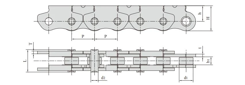
Anti-backbend chain with F10 attachment, P12.7F10SB (12.700 mm pitch)
| Chain No. | Pitch | Roller diameter |
Width between nner plates |
Pin diameter |
Pin length |
Plate dimension |
Tensile strength |
Weight per meter |
||
| P | d1 max |
b1 min |
d2 max |
L max |
H max |
h | t/T | Q min |
q | |
| mm | mm | mm | mm | mm | mm | mm | mm | kN/lbf | kg/m | |
| P12.7F10SB | 12.700 | 7.75 | 4.10 | 4.09 | 12.5 | 13.8 | 8.7 | 1.5 | 8.2/1843 | 0.62 |
Anti-backbend chain with F12 attachment, P12.7F12 (12.700 mm pitch)

| Chain No. | Pitch | Roller diameter |
Width between inner plates |
Pin diameter |
Pin length |
Plate dimension |
Tensile strength |
Weight per meter |
||
| P | d1 max |
b1 min |
d2 max |
L max |
H max |
h | t/T | Q min |
q | |
| mm | mm | mm | mm | mm | mm | mm | mm | kN/lbf | kg/m | |
| P12.7F12 | 12.700 | 7.75 | 5.25 | 3.58 | 13.4 | 12.0 | 7.5 | 1.5 | 10.0/2248 | 0.68 |
Anti-backbend chain, P20SB (20.000 mm pitch)

| Chain No. | Pitch | Roller diameter |
Width between inner plates |
Pin diameter |
Pin length |
Plate dimension |
Tensile strength |
Weight per meter |
||
| P | d1 max |
b1 min |
d2 max |
L max |
H max |
h | t/T | Q min |
q | |
| mm | mm | mm | mm | mm | mm | mm | mm | kN/lbf | kg/m | |
| P20SB | 20.000 | 11.80 | 13.00 | 6.00 | 28.0 | 25.5 | 16.0 | 3.0 | 36.0/8093 | 2.78 |
Anti-backbend chain with F1 attachment, P20SBF1 (20.000 mm pitch)
| Chain No. | Pitch | Roller diameter |
Width between inner plates |
Pin diameter |
Pin length |
Plate dimension |
Tensile strength |
Weight per meter |
||
| P | d1 max |
b1 min |
d2 max |
L max |
H max |
h | t/T | Q min |
q | |
| mm | mm | mm | mm | mm | mm | mm | mm | kN/lbf | kg/m | |
| P20SBF1 | 20.000 | 11.80 | 13.00 | 6.00 | 28.0 | 25.5 | 16.0 | 3.0 | 36.0/8093 | 2.79 |
Side Bow Chains
A side bow chain is built so that it can bend laterally as well as around its sprockets, which means the chain path does not have to be a straight line between two wheels. Because of that, the tables for this family carry two columns an ordinary roller chain never needs: R1 and R2, the side bow radius. Across the models below the specified radius runs from 300 mm on the 06BSBF1 to 2,000 mm on the C24BSB, a range wide enough to cover a tight guide curve and a long, gentle return path on the same page. Models marked with # are supplied with straight side plates.
Side bow chain, 40SB to C2062F6SB series (12.700 mm to 38.100 mm pitch)

| Chain No. | Pitch | Roller diameter |
Width between inner plates |
Pin diameter |
Pin length |
Inner plate depth |
Plate thickness |
Side bow radius |
Tensile strength |
Average tensile strength |
Weight per meter |
|
| P | d1 max |
b1 min |
d2 max |
L max |
Lc max |
h2 max |
t/T max |
R | Q min |
Qo | q | |
| mm | mm | mm | mm | mm | mm | mm | mm | mm | kN/lbf | kN | kg/m | |
| 40SB | 12.700 | 7.95 | 7.85 | 3.96 | 16.9 | 18.1 | 11.7 | 1.50 | 350 | 13.8/3136 | 15.20 | 0.80 |
| 43SB | 12.700 | 7.95 | 7.85 | 3.45 | 18.3 | 19.5 | 11.7 | 1.50 | 305 | 12.0/2727 | 13.20 | 0.64 |
| 50SB | 15.875 | 10.16 | 9.40 | 4.37 | 20.7 | 22.7 | 14.9 | 2.03 | 400 | 20.6/4681 | 22.70 | 1.09 |
| 60SB | 19.050 | 11.91 | 12.57 | 5.34 | 26.6 | 28.4 | 18.0 | 2.42 | 500 | 15.7/3568 | 17.30 | 1.54 |
| 63SB | 19.050 | 11.91 | 12.68 | 5.08 | 28.8 | 30.6 | 17.2 | 2.42/2.03 | 350 | 12.5/2840 | 20.00 | 1.40 |
| 80SB | 25.400 | 15.88 | 15.75 | 7.19 | 34.0 | 37.3 | 24.0 | 3.25 | 711 | 40.9/9201 | 42.00 | 2.60 |
| #06BSBF1 | 9.525 | 6.35 | 5.72 | 3.05 | 13.5 | 15.0 | 8.2 | 1.30 | 300 | 8.0/1818 | 8.80 | 0.60 |
| 08BSB | 12.700 | 8.51 | 7.75 | 3.97 | 17.4 | 18.7 | 11.8 | 1.60 | 400 | 14.0/3182 | 15.40 | 0.70 |
| 08BSBF1 | 12.700 | 8.51 | 7.75 | 3.97 | 16.3 | 17.6 | 11.8 | 1.60/1.20 | 400 | 12.8/2909 | 14.10 | 0.65 |
| 10BSB | 15.875 | 10.16 | 9.65 | 4.50 | 20.1 | 21.5 | 14.7 | 1.70 | 400 | 15.6/3545 | 17.20 | 0.93 |
| 12BSR | 19.050 | 12.07 | 11.68 | 5.12 | 23.1 | 24.8 | 16.0 | 1.85 | 500 | 20.5/4658 | 22.60 | 1.16 |
| 16BSB | 25.400 | 15.88 | 17.22 | 7.90 | 36.5 | 39.7 | 21.0 | 3.70/3.00 | 500 | 55.6/12635 | 64.00 | 2.53 |
| 16BSBF3 | 25.400 | 15.88 | 17.02 | 7.85 | 36.2 | 38.9 | 21.0 | 3.80/3.00 | 1260 | 55.6/12635 | 64.00 | 2.73 |
| #C24BSB | 38.100 | 25.40 | 25.50 | 14.00 | 54.3 | 58.5 | 33.2 | 6.00/4.80 | 2000 | 160.0/35968 | 176.00 | 7.46 |
| #C2050SB | 31.750 | 10.16 | 9.40 | 5.08 | 21.3 | 22.6 | 15.0 | 2.03 | 800 | 21.8/4954 | 24.00 | 0.84 |
| #C2060SBF1 | 38.100 | 11.91 | 12.57 | 5.08 | 26.8 | 28.8 | 18.0 | 2.42 | 800 | 21.8/4954 | 24.00 | 1.17 |
| #C2062F6SB | 38.100 | 22.23 | 12.57 | 5.34 | 26.6 | 29.0 | 23.0 | 2.42 | 1100 | 15.7/3568 | 17.30 | 2.27 |
| #Straight side plates | ||||||||||||
Side Bow Chains with Attachments
These are the same side bow construction with an attachment plate added, for the cases where the moving part has to be bolted to the chain rather than carried on top of it. Three attachment positions are listed, 43SBF11, 43SBF12 and 43SBF13, all on a 12.7 mm pitch chain with a side bow radius of 254 mm. They differ in the height of the attachment, which is why choosing between them is a question about your fixture rather than about the chain.
Side bow chain with attachments, 43SBF11 to 43SBF13 (12.7 mm pitch)

| Chain No. | Pitch | Roller diameter |
Width between inner plates |
Pin diameter |
Pin length |
Inner plate depth |
Attachment dimension | Side bow radius |
||||||
| P | d1 | b1 | d2 | L | h2 | H | H1 | t/T | T1 | G | G1 | W | R | |
| mm | mm | mm | mm | mm | mm | mm | mm | mm | mm | mm | mm | mm | mm | |
| 43SBF11 | 12.7 | 7.95 | 7.85 | 3.45 | 19.6 | 9.8 | 6.9 | 9.2 | 1.5/2.8 | 3 | 25.7 | 31.75 | 31.6 | 254 |
| 43SBF12 | 12.7 | 7.95 | 7.85 | 3.45 | 19.6 | 9.8 | 6.9 | 9.2 | 1.5/2.8 | 3 | 25.7 | 36.00 | 31.6 | 254 |
| 43SBF13 | 12.7 | 7.95 | 7.85 | 3.45 | 19.6 | 9.8 | 6.9 | 9.2 | 1.5/2.8 | 3 | 25.7 | 64.00 | 31.6 | 254 |
Self-Tooth-Forming Chains (P.I.V.)
A self-tooth-forming chain does not mesh with a sprocket. Instead the plates themselves form the teeth and run against a pair of friction plates, which is what makes a stepless drive possible. The tables therefore describe the drive rather than the chain alone, quoting the width over the friction plate (Lf) and the friction plate angle (alpha), given as 15 degrees for every model in this range. Pitch runs from 18.75 mm on the A0 up to 36.00 mm on the A5, with minimum tensile strength rising from 9.0 kN to 71.0 kN across the five sizes.
Self-tooth-forming chain (P.I.V.), A0 to A5 (18.75 mm to 36.00 mm pitch)

| JB Chain No. |
Pitch | Pin diameter |
Pin length |
Plate depth |
Plate thickness |
Width over frictian plate |
Angle of friction plate |
Tensile strength |
Average tensile strength |
Weight per meter |
| P | d2 max |
L max |
h2 max |
T max |
Lf | α | Q min |
Q0 | q | |
| mm | mm | mm | mm | mm | mm | kN/lbf | kN | kg/m | ||
| A0 | 18.75 | 3.00 | 19.5 | 9.5 | 1.0 | 24.0 | 15° | 9.0/2045 | 9.9 | 1.00 |
| A1(A2) | 25.00 | 3.00 | 30.1 | 13.5 | 1.5 | 37.8 | 15° | 21.0/4772 | 23.3 | 2.23 |
| A3 | 28.60 | 3.00 | 35.3 | 16.0 | 1.5 | 44.2 | 15° | 38.5/8750 | 42.7 | 3.04 |
| A4 | 36.00 | 4.00 | 48.5 | 20.5 | 1.5 | 58.5 | 15° | 61.5/13977 | 68.2 | 5.54 |
| A5 | 36.00 | 4.00 | 60.5 | 20.5 | 1.5 | 70.0 | 15° | 71.0/16136 | 78.8 | 6.70 |
Chain Couplings
A chain coupling is a piece of duplex roller chain wrapped around two coupling sprockets. Connection and disconnection both happen at the chain joint, which is why this design is chosen wherever a machine has to be split for maintenance, or wherever two shafts have to be joined without the precision a rigid coupling demands. Four ranges are listed below: complete couplings from the C-3012 on 06B-2 chain up to the C-12022 on 120-2 chain, then the individual series that go with them, from 12.700 mm up to 38.100 mm pitch.
Chain coupling, C-3012 to C-12022 (06B-2 to 120-2 duplex chain)
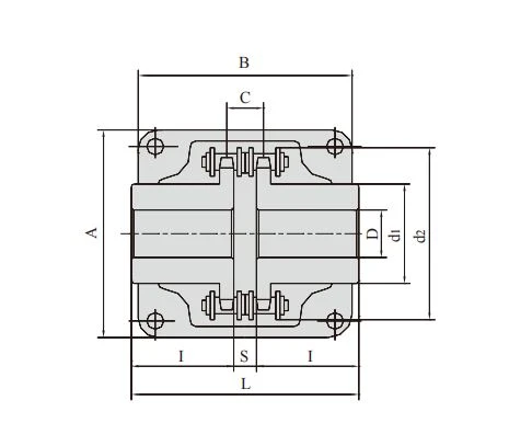
| Chain coupling No. |
Chain No. | Bore Dia |
Dimension | Inertia | Approx Weight |
Casing | ||||||||
| Min | Max | L | I | S | d1 | d2 | C | ×10-3 | Dimension | Approx Weight | ||||
| A | B | |||||||||||||
| mm | mm | mm | mm | mm | mm | mm | mm | kgf·m² | kg | mm | mm | kg | ||
| C-3012 | 06B-2X12 | 12 | 16 | 64.8 | 29.8 | 5.2 | 25 | 45 | 10.2 | 0.233 | 0.4 | 69 | 63 | 0.3 |
| C-4012 | 40-2X12 | 12 | 22 | 79.4 | 36.0 | 7.4 | 35 | 61 | 14.4 | 1.020 | 0.8 | 77 | 72 | 0.3 |
| C-4014 | 40-2X14 | 12 | 28 | 79.4 | 36.0 | 7.4 | 43 | 69 | 14.4 | 1.924 | 1.1 | 84 | 75 | 0.4 |
| C-4016 | 40-2X16 | 14 | 32 | 87.4 | 40.0 | 7.4 | 50 | 77 | 14.4 | 3.285 | 1.4 | 92 | 75 | 0.4 |
| C-5014 | 50-2X14 | 16 | 35 | 99.7 | 45.0 | 9.7 | 53 | 86 | 18.1 | 6.010 | 2.2 | 101 | 85 | 0.5 |
| C-5016 | 50-2X16 | 16 | 40 | 99.7 | 45.0 | 9.7 | 60 | 96 | 18.1 | 9.720 | 2.7 | 111 | 85 | 0.6 |
| C-5018 | 50-2X18 | 16 | 45 | 99.7 | 45.0 | 9.7 | 70 | 106 | 18.1 | 15.420 | 3.8 | 122 | 85 | 0.8 |
| C-6018 | 60-2X18 | 20 | 56 | 123.5 | 56.0 | 11.5 | 85 | 128 | 22.8 | 40.210 | 6.2 | 142 | 106 | 1.2 |
| C-6020 | 60-2X20 | 20 | 60 | 123.5 | 56.0 | 11.5 | 98 | 140 | 22.8 | 62.870 | 7.8 | 158 | 105 | 1.6 |
| C-6022 | 60-2X22 | 20 | 71 | 123.5 | 56.0 | 11.5 | 110 | 152 | 22.8 | 93.450 | 10.4 | 168 | 117 | 1.8 |
| C-8018 | 80-2X18 | 20 | 80 | 141.2 | 63.0 | 15.2 | 110 | 170 | 29.3 | 142.030 | 12.7 | 190 | 129 | 2.5 |
| C-8020 | 80-2X20 | 20 | 90 | 145.2 | 65.0 | 15.2 | 120 | 186 | 29.3 | 204.900 | 16.0 | 210 | 137 | 2.9 |
| C-8022 | 80-2X22 | 20 | 100 | 157.2 | 71.0 | 15.2 | 140 | 202 | 29.3 | 341.170 | 20.2 | 226 | 137 | 3.6 |
| C-10020 | 100-2X20 | 25 | 110 | 178.8 | 80.0 | 18.8 | 160 | 233 | 35.8 | 646.290 | 33.0 | 281 | 153 | 4.6 |
| C-12018 | 120-2X18 | 35 | 125 | 202.7 | 90.0 | 22.7 | 170 | 256 | 45.4 | 1075.710 | 47.0 | 307 | 181 | 6.2 |
| C-12022 | 120-2X22 | 35 | 140 | 222.7 | 100.0 | 22.7 | 210 | 304 | 45.4 | 2454.500 | 72.0 | 357 | 181 | 8.0 |
Chain coupling series, 4012 to 12022 (12.700 mm to 38.100 mm pitch)

| Chain No. | Pitch | Roller diameter |
Width between inner plates |
Pin diameter |
Pin length |
Inner plate depth |
Plate thickness |
Transverse pitch |
Tensile strength |
Average tensile strength |
Weight per piece |
|
| P | d1 max |
b1 min |
d2 max |
L max |
Lc max |
h2 max |
T max |
Pt | Q min |
Q0 | q | |
| mm | mm | mm | mm | mm | mm | mm | mm | mm | kN/lbf | kN | kg/pc | |
| 4012 | 12.700 | 7.95 | 7.85 | 3.96 | 31.0 | 32.2 | 12.00 | 1.50 | 14.38 | 28.2/6409 | 35.9 | 0.20 |
| 4014 | 12.700 | 7.95 | 7.85 | 3.96 | 31.0 | 32.2 | 12.00 | 1.50 | 14.38 | 28.2/6409 | 35.9 | 0.23 |
| 4016 | 12.700 | 7.95 | 7.85 | 3.96 | 31.0 | 32.2 | 12.00 | 1.50 | 14.38 | 28.2/6409 | 35.9 | 0.26 |
| 5014 | 15.875 | 10.16 | 9.40 | 5.08 | 38.9 | 40.4 | 15.09 | 2.03 | 18.11 | 44.4/10091 | 58.1 | 0.49 |
| 5016 | 15.875 | 10.16 | 9.40 | 5.08 | 38.9 | 40.4 | 15.09 | 2.03 | 18.11 | 44.4/10091 | 58.1 | 0.56 |
| 5018 | 15.875 | 10.16 | 9.40 | 5.08 | 38.9 | 40.4 | 15.09 | 2.03 | 18.11 | 44.4/10091 | 58.1 | 0.63 |
| 6018 | 19.050 | 11.91 | 12.57 | 5.94 | 48.8 | 50.5 | 18.00 | 2.42 | 22.78 | 63.6/14455 | 82.1 | 1.06 |
| 6020 | 19.050 | 11.91 | 12.57 | 5.94 | 48.8 | 50.5 | 18.00 | 2.42 | 22.78 | 63.6/14455 | 82.1 | 1.18 |
| 6022 | 19.050 | 11.91 | 12.57 | 5.94 | 48.8 | 50.5 | 18.00 | 2.42 | 22.78 | 63.6/14455 | 82.1 | 1.30 |
| 8018 | 25.400 | 15.88 | 15.75 | 7.92 | 62.7 | 64.3 | 24.00 | 3.25 | 29.29 | 113.4/25773 | 141.8 | 2.38 |
| 8020 | 25.400 | 15.88 | 15.75 | 7.92 | 62.7 | 64.3 | 24.00 | 3.25 | 29.29 | 113.4/25773 | 141.8 | 2.65 |
| 8022 | 25.400 | 15.88 | 15.75 | 7.92 | 62.7 | 64.3 | 24.00 | 3.25 | 29.29 | 113.4/25773 | 141.8 | 2.91 |
| 10018 | 31.750 | 19.05 | 18.90 | 9.53 | 76.4 | 80.5 | 30.00 | 4.00 | 35.76 | 177.0/40227 | 219.4 | 4.51 |
| 10022 | 31.750 | 19.05 | 18.90 | 9.53 | 76.4 | 80.5 | 30.00 | 4.00 | 35.76 | 177.0/40227 | 219.4 | 5.51 |
| 12018 | 38.100 | 22.23 | 25.22 | 11.10 | 95.8 | 99.7 | 35.70 | 4.80 | 45.44 | 254.0/57727 | 314.9 | 8.14 |
| 12022 | 38.100 | 22.23 | 25.22 | 11.10 | 95.8 | 99.7 | 35.70 | 4.80 | 45.44 | 254.0/57727 | 314.9 | 9.95 |
Chain coupling series, 08AF36 to 16AF121 (12.700 mm to 25.400 mm pitch)

| Chain No. | Pitch | Roller diameter |
Width between inner plates |
Pin diameter |
Pin length |
Inner plate depth |
Plate thickness |
Tensile strength |
Average tensile strength |
Weight per piece |
|
| P | d1 max |
b1 min |
d2 max |
L max |
Lc max |
h2 max |
T max |
Q min |
Q0 | q | |
| mm | mm | mm | mm | mm | mm | mm | mm | kN/lbf | kN | kg/m | |
| 08AF36 | 12.700 | 7.95 | 21.70 | 3.96 | 30.8 | 32.1 | 12.00 | 1.50 | 13.8/3135 | 16.20 | 1.070 |
| 10AF13 | 15.875 | 10.16 | 16.31 | 5.08 | 27.6 | 29.1 | 15.09 | 2.03 | 22.2/5045 | 27.50 | 1.350 |
| 10AF71 | 15.875 | 10.16 | 19.00 | 5.08 | 30.5 | 32.2 | 15.09 | 2.03 | 21.8/4901 | 24.40 | 1.480 |
| *10AF75 | 15.875 | 10.16 | 45.60 | 5.08 | 57.0 | 58.5 | 15.09 | 2.03 | 21.8/4901 | 24.40 | 2.540 |
| 12AF2 | 19.050 | 11.91 | 19.10 | 5.94 | 32.6 | 34.4 | 18.00 | 2.42 | 31.8/7227 | 38.20 | 1.900 |
| 12AF6 | 19.050 | 11.91 | 18.80 | 5.94 | 31.9 | 33.5 | 18.00 | 2.42 | 31.8/7227 | 38.20 | 1.870 |
| 12AF26 | 19.050 | 11.91 | 19.36 | 5.94 | 31.9 | 33.5 | 18.00 | 2.42 | 31.8/7227 | 38.20 | 1.940 |
| 12AF34 | 19.050 | 11.91 | 19.00 | 5.94 | 31.9 | 31.9 | 18.00 | 2.42 | 31.1/7066 | 38.20 | 1.860 |
| 12AF54 | 19.050 | 11.91 | 19.50 | 5.84 | 31.9 | 31.9 | 18.00 | 2.29 | 31.1/7066 | 38.20 | 1.607 |
| *12AF97 | 19.050 | 11.91 | 35.35 | 5.94 | 48.8 | 50.5 | 18.00 | 2.42 | 31.8/7149 | 38.20 | 2.630 |
| *12AF101 | 19.050 | 11.91 | 37.64 | 5.94 | 51.2 | 52.9 | 18.00 | 2.42 | 31.8/7149 | 38.20 | 1.990 |
| *12AF124 | 19.050 | 11.91 | 20.57 | 5.94 | 33.9 | 35.7 | 18.00 | 2.42 | 31.8/7149 | 38.20 | 1.910 |
| 16AF25 | 25.400 | 15.88 | 25.58 | 7.92 | 42.4 | 43.9 | 24.00 | 3.25 | 56.7/12886 | 63.50 | 3.260 |
| *16AF40 | 25.400 | 15.88 | 70.00 | 7.92 | 87.6 | 91.1 | 24.00 | 3.25 | 56.7/12886 | 63.50 | 5.780 |
| *16AF46 | 25.400 | 15.88 | 36.00 | 7.92 | 53.3 | 56.8 | 24.00 | 3.25 | 56.7/12886 | 63.50 | 3.880 |
| *16AF75 | 25.400 | 15.88 | 56.00 | 7.92 | 73.5 | 76.9 | 24.00 | 3.25 | 56.7/12746 | 63.50 | 5.110 |
| *16AF111 | 25.400 | 15.88 | 45.00 | 7.92 | 62.7 | 65.8 | 24.00 | 3.25 | 56.7/12746 | 63.50 | 4.480 |
| *16AF121 | 25.400 | 15.88 | 73.50 | 7.92 | 91.3 | 94.7 | 24.00 | 3.25 | 56.7/12746 | 63.50 | 6.000 |
| *The number of roller depends upon the specific application | |||||||||||
Chain coupling series, 06BF27 to 24BF33 (9.525 mm to 38.100 mm pitch)
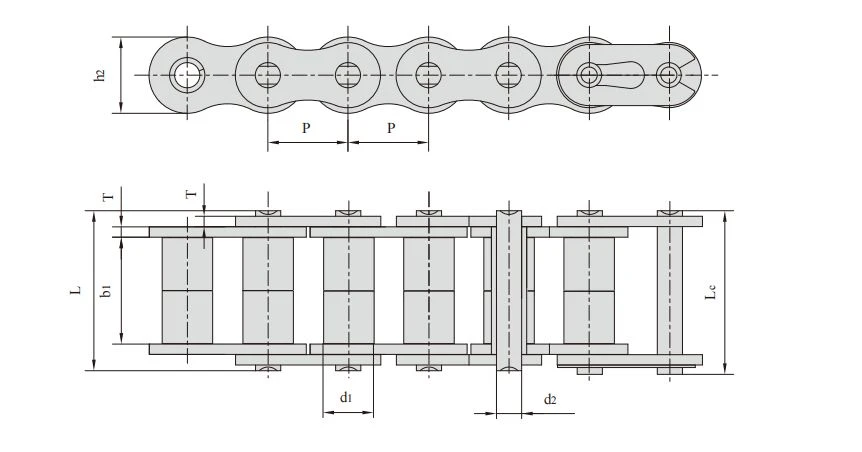
| Chain No. | Pitch | Roller diameter |
Width between inner plates |
Pin diameter |
Pin length |
Inner plate depth |
Plate thickness |
Tensile strength |
Average tensile strength |
Weight per meter |
|
| P | d1 max |
b1 min |
d2 max |
L max |
Lc max |
h2 max |
T max |
Q min |
Q0 | q | |
| mm | mm | mm | mm | mm | mm | mm | mm | kN/lbf | kN | kg/m | |
| *20AF44 | 31.750 | 19.05 | 32.00 | 9.53 | 53.5 | 57.8 | 30.00 | 4.00 | 86.7/19490 | 99.70 | 4.820 |
| *24AF27 | 38.100 | 22.23 | 75.92 | 11.10 | 101.0 | 105.0 | 35.70 | 4.80 | 124.6/28010 | 143.20 | 9.810 |
| *06BF27 | 9.525 | 6.35 | 18.80 | 3.28 | 26.5 | 28.2 | 8.20 | 1.30 | 9.0/2045 | 9.63 | 0.770 |
| *06BF31 | 9.525 | 6.35 | 16.40 | 3.28 | 23.4 | 24.4 | 8.20 | 1.30 | 9.0/2045 | 9.63 | 0.660 |
| *06BF71 | 9.525 | 6.35 | 16.50 | 3.28 | 24.5 | 25.6 | 8.20 | 1.30 | 9.0/2023 | 9.63 | 0.830 |
| 08BF97 | 12.700 | 8.51 | 15.50 | 4.45 | 24.8 | 26.2 | 11.80 | 1.60 | 18.0/4989.6 | 19.20 | 0.980 |
| *08BF129 | 12.700 | 8.51 | 35.80 | 4.45 | 45.1 | 46.1 | 11.80 | 1.60 | 18.0/4989.6 | 19.02 | 1.500 |
| 10BF21 | 15.875 | 10.16 | 42.83 | 5.08 | 52.7 | 54.1 | 14.70 | 1.70 | 22.0/5000 | 25.30 | 2.260 |
| 10BF43 | 15.875 | 7.03 | 27.80 | 5.08 | 39.0 | 40.6 | 14.70 | 2.03 | 22.4/5090 | 25.76 | 1.140 |
| *10BF43-S | 15.875 | 10.00 | 27.80 | 5.08 | 39.0 | 40.6 | 14.70 | 2.03 | 22.4/5090 | 25.76 | 1.800 |
| *16BF75 | 25.400 | 15.88 | 27.50 | 8.28 | 47.4 | 50.5 | 21.00 | 4.15/3.10 | 60.0/13488 | 66.00 | 3.420 |
| *16BF87 | 25.400 | 15.88 | 35.00 | 8.28 | 54.1 | 55.6 | 21.00 | 4.15/3.10 | 60.0/13488 | 66.00 | 3.840 |
| *16BF114 | 25.400 | 15.88 | 49.90 | 8.28 | 69.0 | 72.0 | 21.00 | 4.15/3.10 | 60.0/13488 | 66.00 | 4.740 |
| *20BF45 | 31.750 | 19.05 | 55.01 | 10.19 | 76.8 | 80.5 | 26.40 | 4.50/3.50 | 95.0/21356 | 104.50 | 6.350 |
| *24BF33 | 38.100 | 25.40 | 73.16 | 14.63 | 101.7 | 106.2 | 33.20 | 6.00/4.80 | 160.0/35968 | 176.00 | 11.840 |
| *The number of roller depends upon the specific application | |||||||||||
Bush Chains
In a bush chain the load is carried on the bush rather than on a roller. That suits the slower, heavier end of the duty range, where a roller would be crushed or simply is not needed. The bush chains below start at 15.000 mm pitch on the P15F1-B and run up to 80.000 mm pitch on the P80-B, with minimum tensile strength climbing from 12.5 kN to 315.0 kN. The heavier sizes are the ones that show up on steelworks, cement and bulk handling drives, where the chain is judged on how long it lasts rather than how quiet it runs.
Bush chain, P15F1-B to P80-B (15.000 mm to 80.000 mm pitch)

| Chain No. | Pitch | Bush diameter |
Width between inner plates |
Pin diameter |
Pin length |
Plate depth |
Plate thickness |
Tensile strength |
Average tensile strength |
Weight per meter |
|
| P | d1 max |
b1 min |
d2 max |
L max |
Lc max |
h2 max |
T max |
Q min |
Q0 | q | |
| mm | mm | mm | mm | mm | mm | mm | mm | kN/lbf | kN | kg/m | |
| P15F1-B | 15.000 | 9.00 | 14.0 | 6.0 | 25.3 | 30.0 | 14.0 | 2.03 | 12.5/2852.5 | 13.75 | 1.150 |
| P20-B | 20.000 | 12.00 | 16.0 | 8.0 | 33.0 | 36.0 | 18.0 | 3.00 | 25.0/5624 | 27.50 | 2.140 |
| P20F3-B | 20.000 | 12.00 | 16.0 | 8.0 | 33.0 | 36.0 | 19.0 | 3.00 | 25.0/5624 | 27.50 | 2.030 |
| *PZ20-B | 20.000 | 12.00 | 16.0 | 8.0 | 33.0 | 34.7 | 18.0 | 3.00 | 25.0/5624 | 27.50 | 2.253 |
| P25-B | 25.000 | 15.00 | 18.0 | 10.0 | 35.0 | 39.0 | 24.0 | 3.00 | 31.5/7086 | 34.70 | 3.170 |
| P25F1-B | 25.000 | 15.00 | 18.0 | 10.0 | 35.0 | 39.0 | 24.0 | 3.00 | 31.5/7086 | 34.70 | 2.670 |
| P30F2-B | 30.000 | 17.00 | 20.0 | 11.0 | 41.0 | 45.4 | 28.0 | 4.00 | 40.0/8998 | 44.00 | 4.250 |
| P30F6-B | 30.000 | 17.00 | 20.0 | 11.0 | 42.4 | 46.0 | 28.0 | 4.00 | 40.0/8998 | 44.00 | 3.750 |
| P35F2-B | 35.000 | 18.00 | 22.0 | 12.0 | 44.5 | 48.0 | 30.0 | 4.00 | 50.0/11248 | 55.00 | 4.330 |
| P35F5-B | 35.000 | 18.00 | 22.0 | 12.0 | 44.5 | 48.0 | 30.0 | 4.00 | 50.0/11248 | 55.00 | 3.770 |
| P36-B | 36.000 | 18.00 | 22.0 | 12.5 | 44.5 | 49.0 | 30.0 | 4.00 | 60.0/13497 | 66.00 | 4.200 |
| P40-B | 40.000 | 20.00 | 25.0 | 14.0 | 52.4 | 57.0 | 35.0 | 5.00 | 63.0/14172 | 69.30 | 5.430 |
| P45-B | 45.000 | 22.00 | 30.0 | 16.0 | 62.0 | 66.5 | 40.0 | 6.00 | 80.0/17996 | 88.00 | 7.540 |
| P50-B | 50.000 | 26.00 | 35.0 | 18.0 | 68.0 | 73.5 | 44.0 | 6.00 | 100.0/22495 | 110.00 | 8.900 |
| P55-B | 55.000 | 30.00 | 45.0 | 20.0 | 88.0 | 93.5 | 49.0 | 8.00 | 125.0/28119 | 137.50 | 13.920 |
| P55F1-B | 55.000 | 30.00 | 45.0 | 20.0 | 88.0 | 110.0 | 49.0 | 8.00 | 125.0/28119 | 137.50 | 13.920 |
| P55F4-B | 55.000 | 28.00 | 45.0 | 20.0 | 88.0 | 93.5 | 43.0 | 8.00 | 125.0/28100 | 137.50 | 12.400 |
| P60-B | 60.000 | 32.00 | 50.0 | 22.0 | 94.1 | 99.5 | 55.0 | 8.00 | 160.0/35993 | 176.00 | 15.200 |
| P65-B | 65.000 | 36.00 | 56.0 | 26.0 | 97.5 | 113.0 | 61.0 | 8.00 | 200.0/44960 | 220.00 | 18.900 |
| P70-B | 70.000 | 30.00 | 65.0 | 30.0 | 117.0 | 130.0 | 67.0 | 10.00 | 250.0/57050 | 275.00 | 26.270 |
| P80-B | 80.000 | 44.00 | 70.0 | 32.0 | 131.0 | 150.0 | 75.0 | 12.00 | 315.0/71883 | 346.00 | 31.800 |
| P19.05 | 19.050 | 12.70 | 12.5 | 7.5 | 31.6 | 33.6 | 20.0 | 4.15/3.25 | 50.0/11248 | 55.00 | 2.560 |
| P19.05F50-B | 19.050 | 11.91 | 12.9 | 7.5 | 31.6 | 34.8 | 20.0 | 4.15/3.25 | 40.0/8992 | 44.00 | 2.530 |
| P22.225F10-B | 22.225 | 14.30 | 14.6 | 9.0 | 36.3 | 39.3 | 23.5 | 4.80/4.00 | 55.0/12364 | 60.50 | 3.580 |
| P22.225F3-B | 22.225 | 15.60 | 14.6 | 9.0 | 36.3 | 38.0 | 23.5 | 4.80/4.00 | 75.0/16860 | 82.50 | 3.750 |
| P25.4F21-B | 25.400 | 15.88 | 16.0 | 10.0 | 42.5 | - | 26.8 | 5.60/4.80 | 80.0/17984 | 88.00 | 4.700 |
| P31.75F5-B | 31.750 | 19.05 | 20.0 | 11.1 | 46.0 | 50.0 | 33.5 | 5.60/4.80 | 100.0/22480 | 110.00 | 5.980 |
| *P42.27F1-B | 42.270 | 13.00 | 22.9 | 7.92 | 41.0 | 45.8 | 24.0 | 3.20 | 42.3/9509 | 46.50 | 2.360 |
| *P50.8F7 | 50.800 | 18.50 | 25.0 | 14.5 | 53.5 | 57.5 | 40.0 | 5.00 | 120.0/26994 | 132.00 | 6.300 |
| *Straight side plates | |||||||||||
Materials and Construction
Pitch alone tells you nothing about duty. What matters is the combination of pitch, plate thickness and tensile strength, and this page spans a wider spread than any other in the catalogue: plate thickness from 1.04 mm on the 06BF34 up to 12.00 mm on the P80-B, and minimum tensile strength from 5.8 kN on the 06CF37SB up to 315.0 kN on the same 80 mm bush chain. Read the three numbers together before comparing two models.
Link plates and pins. Plates carry the working load and set the fatigue life of the chain. Plates and pins are hardened under vacuum quenching, and the factory works to DIN, ANSI and ISO practice.
Attachments are part of the part number. The F-number in a model such as P12.7F10SB is the attachment type. F1, F3, F5, F6, F7, F10, F11, F12, F13, F21, F45 and F50 all appear in the tables below, and two chains with the same pitch and different F-numbers are not interchangeable.
Straight side plates where there is no room to spare. Models marked with a hash in the tables are supplied with straight side plates, which keep the chain narrower across the pin ends.
Tell us the working environment, the load and the speed, and the build is confirmed against the duty rather than against the price list.
Where These Chains Are Used
Pushing windows, hatches and vents. The anti-backbend family exists for drives that have to push. Automated window and roof vent actuators, hatch and skylight gear, and any mechanism where the load sits away from the drive and has to be driven outward are the classic applications.
Chain paths that are not straight. Side bow chains are used where the chain has to turn a corner or follow a curved guide within its own plane, including long return runs and machines where the sprocket line cannot be kept straight.
Stepless drives. Self-tooth-forming chains are used for variable speed drives, where the friction plate angle and the width over the friction plate matter more than the chain pitch.
Joining two shafts. Chain couplings are used to connect a motor or gearbox output to a driven shaft, and they are preferred where the machine is split for service. Because disconnection happens at the chain joint, maintenance is a matter of removing one link rather than moving a shaft.
Slow, heavy drives. Bush chains are chosen for the duties where a roller is unnecessary or would not survive: bulk handling, steelworks equipment and heavy conveying at lower speed.
Why Buyers Choose Ocean for These Chains
Six families, one enquiry. Anti-backbend, side bow, side bow with attachments, self-tooth-forming, chain couplings and bush chains all sit on this page, so an enquiry can cover a whole machine rather than a single part.
A spread that covers both ends of the duty range. 9.525 mm to 80.000 mm pitch and 5.8 kN to 315.0 kN in one place, including the straight side plate option and the bush builds where d1 in the table is the outside diameter of the bush.
Side bow radius as a stated specification. Instead of a single nominal figure, the tables give a radius for every model, so you can match the chain to the curve instead of discovering the limit on the machine.
Couplings supplied as a working set. A coupling is only useful if the chain and its sprockets arrive together and match, and the four ranges on this page are ordered as sets.
Built to international standards. DIN, ANSI and ISO practice, with the drawing and the blueprint analysed before production starts, and OEM or ODM development based on your drawing or your sample.
Capacity behind the offer. Ocean Group has operated four specialised factories since 2001 with more than 200 people, supplying transmission parts to customers in over 120 countries, with a 24-hour response commitment and a 12-month standard warranty.
Payment Terms
Payment is agreed on the offer rather than assumed here, so nothing on this page commits you to a method. Two things decide it: the Incoterm you work on, and the method your finance department requires.
Tell us both with the enquiry. If your bank needs a letter of credit, say so at the quotation stage and the offer is built on it from the start instead of being reissued afterwards. If the order is a first custom batch, expect the terms to reflect that the geometry is still unproven; a repeat order against an approved drawing normally moves to simpler and faster terms, because the risk on both sides is lower.
Also worth telling us up front: whether the buyer is the importer of record, whether the documents have to be issued in a particular form, and whether the first order is a trial or a full production run. Each of those changes the offer.
Packing and Shipping
These chains are harder to ship than a plain roller chain, for two reasons. A side bow chain has a minimum radius, and a chain packed tighter than that radius can arrive looking perfectly fine and then run badly. And a chain coupling is not one piece, so the set has to stay together.
State the coil diameter. Tell us the smallest coil your stores can handle, and we confirm it sits above the chain's own stated radius. For the models at the 300 mm end of the range that is a real constraint, not a formality.
Keep sets together. A coupling ships as a chain plus its sprockets, packed as one set and marked as one set, so nothing is separated at goods-in and discovered three weeks later.
Quote the length in pitches. A length in pitches is what the line side will measure, and it is more accurate than a weight, particularly on the attachments.
Protection is agreed, not assumed. If the chain will sit in a container or on a quay for weeks, say whether you want added rust-preventive protection. It is quoted when you ask for it and left out when you do not.
Marking and documents. Every package carries the model number, quantity and length, and the packing list repeats them.
Freight. Give us the destination port and the Incoterm and the offer shows freight on that basis, or we ship against your own nominated forwarder.
Quality Standards and Inspection
The factory works to DIN, ANSI and ISO practice, holds ISO 9001, and hardens plates and pins under vacuum quenching. The drawing and the blueprint are analysed before production starts.
For a first order the sequence that avoids arguments is this: send the drawing or the sample, receive the dimension sheet, approve it, and let the approved sheet become the reference for the batch. Everything after that is checked against the same sheet.
If your incoming inspection works to defined measurements, tell us which dimensions and which acceptance limits you will measure at goods-in, and agree them before production rather than after delivery. Chains with attachments are the ones where this matters most, because it is the attachment position, not the pitch, that decides whether the chain fits.
What to send with a first order: the drawing or the worn chain, the critical dimensions your inspectors will measure, and the environment the chain runs in.
FAQ
What does an anti-backbend chain actually prevent?
It prevents the chain from folding in the wrong direction. Ordinary chain only pulls; an anti-backbend chain can also push, because the plate shape locks when the chain tries to bend backwards. That is why it is used for pushing windows, hatches and vents.
How do I choose a side bow radius?
The tables give R1 and R2 for each model, and across this range the specified radius runs from 300 mm to 2,000 mm. Send us the tightest curve in your layout and we will confirm which model suits it, rather than you working backwards from a catalogue.
What is a self-tooth-forming chain used for?
A stepless, variable speed drive. The plates form their own teeth against a friction plate instead of engaging a sprocket, so the tables quote the width over the friction plate and the friction plate angle, which is 15 degrees for every model in this range.
Is a chain coupling supplied as a complete unit?
Yes. A chain coupling is a piece of duplex roller chain plus a pair of coupling sprockets, and connection or disconnection is done at the chain joint. The four ranges here are ordered as sets so the chain and the sprockets match.
What do the asterisk and hash marks mean in the tables?
They mean different things in different tables, so read the note at the bottom of each one. Under the anti-backbend table, an asterisk marks a bush chain where d1 is the outside diameter of the bush. Under the side bow table, a hash marks straight side plates. If you are unsure, send us the number and we will confirm.
What is the size range on this page?
Pitch runs from 9.525 mm on the 06BF34 up to 80.000 mm on the P80-B bush chain, and minimum tensile strength from 5.8 kN on the 06CF37SB up to 315.0 kN on the P80-B.
How do I specify an attachment?
By the F-number in the model, for example P12.7F10SB. F1, F3, F5, F6, F7, F10, F11, F12, F13, F21, F45 and F50 all appear on this page. Two chains with the same pitch but different F-numbers will not interchange.
What if I cannot find my model on this page?
Send an enquiry with photographs and a drawing, or with the number stamped on the old plate, and our engineers will identify or match the part. A worn sample works as well as a drawing.
Send Your Drawing or Sample
Anti-backbend, side bow, self-tooth-forming, coupling and bush chains are all engineered families rather than stock items, so the useful first step is the drawing, the worn chain, or the number on the old link. Send whichever you have and the model, the attachment, the plate type and the dimension sheet come back for approval before anything is made.
Hot Tags: other(drive chains), China other(drive chains) manufacturers, suppliers, factory, Double Pitch Transmission Chains, Galvanized Roller Chain, Inverted Tooth Chains, Oil Field Chains, Self lubrication Roller Chains, Short Pitch Precision Roller Chains


